In order for these parts to be assembled correctly and fulfill their function of positioning and guiding the motor and pinion shafts, certain dimensions must be common, hence the importance of using one (or more) master sketches.
These master sketches were made after inserting and scaling flat images of the crankcase, using the Sketcher workbench directly without going into PartDesign, to make them independent of the different crankcase components.
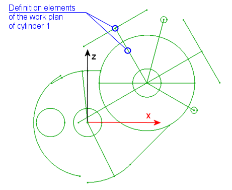
They contain circles and segments whose centers or ends give all the strategic points of the constructions to come (the dimensions or other geometric constraints do not appear on the image because the sketch shown is not in edit mode) .
|
The master sketch 1 which will drive the entire crankcase parts representation project is in the XZ plane.
Its position has been chosen so that its origin is at the center of the bore receiving the gearbox shaft.
Importing external geometry from this sketch will give better stability to the project and the sources will always be the same.
|
|
|
|
Motorcycle engine and gearbox crankases |
|
1- Go to the Image workbench ![]() .
.
2- Import an image or plan view representing the object to be drawn ![]() in the appropriate plane (XY, YZ or XZ).
in the appropriate plane (XY, YZ or XZ).
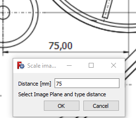
3- Scale the imported image.
To do this, zoom in on the image to display the largest known dimension, click on the ![]() icon, complete the value in the window that has just opened, then click on the image for the end points of the dimension to scale, and finally click on the name of the image in the tree structure and confirm with OK.
icon, complete the value in the window that has just opened, then click on the image for the end points of the dimension to scale, and finally click on the name of the image in the tree structure and confirm with OK.
|
|
Do not forget ! You can reorient or move your image to your liking by right-clicking on its name,
|
|
Master sketch 2 is in the XZ plane.
It will allow you to build the work planes of cylinders 1 and 2 (but sketch 1 can be enough).
It is a simplified and completed carbon copy of sketch 1.
|
|
|
Master sketch 3 is in the XY plane.
Its construction is done without any constraint of verticality or horizontality or horizontal or vertical distances or lengths.
It will make it possible to build the sketches of the cylinder support 1 for the left crankcase, and 2 for the right crankcase.
|
|
|
Master sketch 4 is in the XY plane.
It is a carbon copy of sketch 3 of which 2 or 3 dimensions have been adapted since cylinders 1 and 2 are offset with respect to the XZ plane.
It will make it possible to build the sketches of the cylinder support 2 for the left crankcase, and 1 for the right crankcase.
|
|
|
Master sketch 5 is in the XY plane.
It is an addition to sketch 3 intended to lighten this sketch.
It will make it possible to build the recesses of the cylinder support 1 for the left crankcase, and 2 for the right crankcase.
|
|