For more information, see the wiki of PartDesign ShapeBinder and SubShapeBinder
The example proposes to draw an assembly of pipe flanges with its gasket, all in geometry and related dimensions.
|
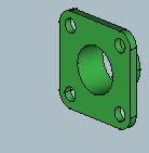
In the first part you will see :
how the 1st flange is constructed.

|
|
|
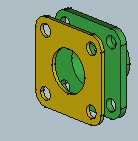
In the second part you will see :
how to create the gasket from a shape bound (ShapeBinder) to the 1st flange.
|
|
|
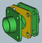
In the third part you will see :
how to use the Asm3 assembly WB to "duplicate" by a link (Link) the 1st flange and link the three parts by geometric constraints.
Differences between ShapeBinder and SubShapeBinder
|
|