|
Click on the icons to know the possible uses of the constraints :
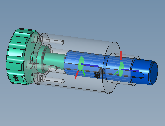
Motion transformation by Screw-nut system (or Screw Joint).
|
Please note :
3 kinematic equivalence classes are required :
- a Base class,
- a Screw class,
- a Nut class.
One of the Screw or Nut classes must be in Revolute Joint with respect to the Base class, the other in Slider Joint with respect to the same Base class.
The axis of rotation of the Revolute Joint and the motion direction of the Slider Joint must be coaxial.

|
|
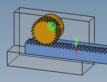
Motion transformation by Rack and Pinion Joint
|
Please note :
3 kinematic equivalence classes are required :
- a Base class,
- a Pinion class,
- a Rack class.
The Pinion class must be in Revolute Joint with respect to the Base class, the Rack class in Slider Joint with the same Base class.
The axis of rotation of the Revolute Joint and the motion direction of the Slider Joint must be perpendicular.
|
|
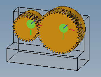
Motion transformation by Gears
|
Please note :
3 kinematic equivalence classes are required :
- a Base class,
- a Pinion 1 class,
- a Pinion 2 class.
Both the classes Pinion 1 and Pinion 2 must be in Revolute Joint to the Base class.
The axes of rotation of the two Revolute Joints must be parallel in the general case, or by a given angle depending on the type of gear.
The two primitive diameters of the gears make it possible to define the transmission ratio of the mechanism.
|
|
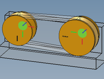
Motion transformation by Pulleys and Belt
|
Please note :
3 kinematic equivalence classes are required :
- a Base class,
- a Pulley 1 class,
- a Pulley 2 class.
Both the classes Pulley 1 and Pulley 2 must be in Revolute Joint to the Base class.
The axes of rotation of the two Revolute Joints must be parallel in the general case, or by a given angle depending on the type of mechanism.
The two primitive diameters of the pulleys make it possible to define the transmission ratio of the mechanism.
|
|
Add a AxialAlignment constraint to align edges / faces of two or more parts.
The constraint acceps linear edges, which become colinear, and planar faces, which are aligned uses their surface normal axis, and cylindrical face, which are aligned using the axial direction. Different types of geometry elements can be mixed.
This tool makes it possible to make the selected parts solid, thus to create a kinematic equivalence class quickly if the components are already correctly positioned in relation to each other.
|
Please note :
NO COMPLETED
|
|
Add a PointInPlane to constrain one or more point inside a plane.
|
2- Tools for motion transformation, and specific tools :
It is good to test these tools to get to know them better.
 Click on the icons to find out about the possible uses of constraints : Click on the icons to find out about the possible uses of constraints :
|
 What constraints to bind parts of an assembly ?