|
Click on the icons to know the possible uses of the constraints :
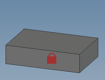
Toggle Grounded : Add a Locked constraint to fix part(s).
|
VERY IMPORTANT :
It is essential to immobilize a part (or subassembly) in the geometric reference system so that the other objects are positioned on it and not the other way around,
otherwise the positioning of the whole thing will be very fanciful for future projections.
All the DOFs of the reference object are eliminated with respect to the project's general coordinate system. (but it is still possible to move/reorient the object (toggle) by temporarily releasing the object).

|
|
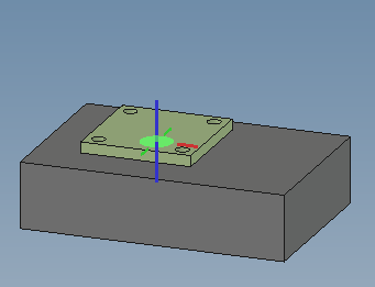
Fixed Joint :
Adds a relative immobilization constraint between two parts. All DOFs between the two parts are eliminated.
|
This constraint positions the parts according to the designated constraint elements : the induced plane faces coincide at their centers (with a possible correction) BUT removing all the DOFs between the two parts.
Please note :
The position of the constrained part in relation to the reference part can be adjusted according to and around the axes related to the reference element : This constraint saves solver resources.
The blue axis is the normal Z that identifies the preponderant plane of the contact (red=X and green=Y).
The two Zs must be coaxial (or parallel).
|
|
Revolute Joint : Adds an alignment constraint between two straight lines (axes) of two parts, keeping only 1 DOF (rotation) around the axis common to the two parts.
|
Please note :
This constraint can use several types of entities : planes, circles, surfaces of revolution...
(normal to a circle passing through its center, axis of surface of revolution and a fixed point on this axis)
It maintains 1 DOF (rotation) around the axis common to the two parts.
The blue axis is the normal Z that identifies the axis of the surface or the edge of the chosen elements (red=X and green=Y).
The two Zs must be coaxial (axis of rotation of the joint).
|
|
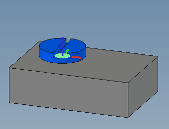
Cylindrical Joint : Adds an alignment constraint between two straight lines (axes) of two parts keeping 2 DOFs around the axis common to the two parts (1 translation and 1 rotation).
|
Please note :
This constraint can use several types of entities: circles, cylindrical surfaces, axes...
(normal to a circle passing through its center, axis of surface of revolution)
It maintains 2 DOF (one rotation and one translation) around and parallel to the axis common to the two parts.
The blue axis is the normal Z that identifies the axis of the surface or the edge of the chosen elements (red=X and green=Y).
The two Zs must be coaxial (axis of rotation of the joint).
|
|
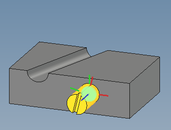
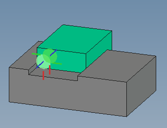
Slider Joint : Adds a constraint for aligning edges/axes of two parts, keeping only 1 DOF (translation) along the axis common to the two parts.
|
Please note :
This constraint accepts linear edges (which become collinear), cylindrical surfaces (which are aligned according to their axes), flat surfaces (whose normals will be made collinear), etc.
Different types of geometric elements can be mixed and different position settings are still possible.
It maintains 1 DOF: the rectilinear translation parallel to the chosen entities.
The blue axis is the normal Z that identifies the plane or edge of the chosen elements (red=X and green=Y).
The two Zs must be coaxial or parallel (direction of translation).
|
|
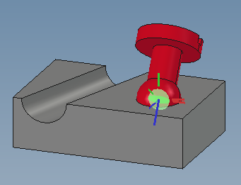
Ball Joint : Adds a coincidence constraint between two points or centers of spheres, keeping the 3 DOFs rotating around the point (center) common to the two pieces.
|
Please note :
This constraint makes it possible to eliminate all degrees of freedom (DOF) in one step except for the 3 rotations around the center of the spherical part.
Any points (vertices) can be used.
The blue axis is always the normal Z (red=X and green=Y).
But here only the origins of the two landmarks are coincidence.
|
|
Distance Constraint : Adds a distance constraint between two entities (points, edges, planes). The DOF eliminated depends on the geometric entities used.
|
Please note :
Each pair of entities gives different results from the point of view of the discarded DOFs. Adjustments are still possible.
This constraint makes it possible to simulate the tangency between a sphere or a cylinder and a plane, two spheres, two cylinders, etc., by adjusting the distance according to the radii concerned.
The blue axis is the normal Z that identifies the plane or edge of the chosen elements (red=X and green=Y).
The two Zs must be parallel for this constraint (unless a point is concerned).
|
|
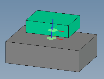
Parallelism Constraint : Adds a parallelism constraint between two entities (planes, edges, axes).
|
Please note :
The result from the point of view of the DOF eliminated depends on the geometric entities chosen for the constraint.
The blue axis is the normal Z that identifies the plane or edge of the chosen elements (red=X and green=Y).
The two Zs must be parallel for this constraint.
|
|
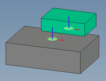
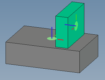
Perpendicularity constraint : Adds a perpendicularity constraint between two entities (planes, edges, axes).
|
Please note :
The result from the point of view of the DOF eliminated depends on the geometric entities chosen for the constraint.
The blue axis is the normal Z that identifies the plane or edge of the chosen elements (red=X and green=Y).
The two Zs must be perpendicular for this constraint.
|
|
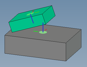
Angle Constraint : Adds an angle constraint between two entities (planes, edges, axes).
|
Please note :
The result from the point of view of the DOF eliminated depends on the geometric entities chosen for the constraint.
The blue axis is the normal Z that identifies the plane or edge of the chosen elements (red=X and green=Y).
The angle of the two Zs is the angle that is imposed by the constraint.
|
|
|
1- The classic constraints
Before using a tool, it is important to know what you can do with it, so to test it.
The constraints presented below make it possible to deal with the majority of cases :
 Click on the icons to find out about the possible uses of constraints : Click on the icons to find out about the possible uses of constraints :
|
 What constraints to bind parts of an assembly ?