This is a mechanism with complex kinematics.
Reflection and interpretation of the information in the “specifications” led me to a first result.
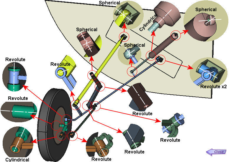
It therefore seems useful to me, if not essential, to have a precise idea of the kinematic diagram of the whole in order to identify the mechanical connections necessary for operation.
Kinematic diagram
This diagram is usually created on paper in 2D
according to one or more views.
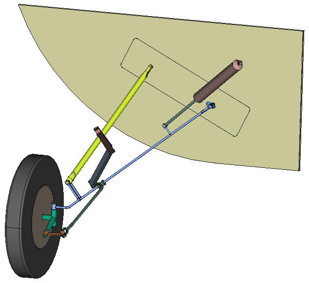
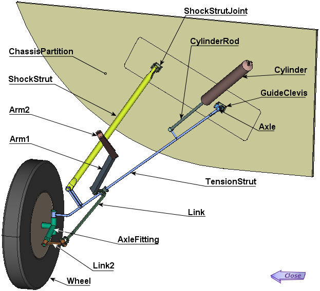
Here it is in 3D:
Notes and assumptions:
- We will assume the shock absorber represented
as a single block, its “crushed” length corresponding
to the wheel axle in a horizontal position.
- The wheel, the cylinder and the shock absorber
being elements of commerce do not need
to be represented “in the design context”
and can be built separately then integrated
in the end in the general assembly.
- The fuselage bulkhead carrying the joints
is already drawn, since it is one of the
elements defined in the specifications.
![]()
![]()
|
|
Project display |
|
Click on picture to enlarge